NETTEST IMPROVES FLYING PROBE TEST
nettest improves the fault coverage and test time
of the flying probe tester.
Preface: this paper deals with the improvement in the fault coverage and the reduction in the test time for testing modules using the flying probe tester (FPT). The effectiveness of the new nettest method can be demonstrated using the example of the short test. Improvement achieved is decisive for extending the range of application of the module prototype test to the production engineering test for small and medium numbers of items.
1. Introduction
2. Test time and fault coverage
of the short test
3. Standard test
4. Nettest
5. Comparison of test times
for standard test and nettest
6. Summary
Bibliography
INTRODUCTION
With the rapid increase in chip and module complexity and the resultant drop in the cost of each functional unit (gate) the design for testability (DFT) and self-test concepts have become increasingly important from an economics point of view. The common feature of these test solutions is: test units (hardware and software) are implemented in electronic modules as early as the development phase. Regardless of whether a structural or functional test is preferred, the embedded test options can be implemented by the production engineering process and product application in all subsequent phases. They are a fixed component of the electronic product.
Standardization of the boundary scan (BS) created the basis for an alternative solution to the in circuit test (ICT). However, over the following years, the disadvantages of the BS concept (development costs, loss of performance, no fault cover for analog circuits, etc.) has meant that a full BS is more the exception than the rule.
In order to support the general trend towards an increase in the component density, a changeover from the ICT to the BS must naturally be supported as the area for test pads disappears completely as a result. However, changing over from ICT to FPT leads to better results due to smaller test pads and a reduction in the space permitted between test pads in comparison with the ICT concept (and resultant demands on testability). The "component density" criterion can be decisive for selecting the test concept "BS+FPT" taking into consideration other boundary conditions (such as the number of items/module type, probability of redesign and time to market).
The often unrealistic demand for a full BS does not apply. The reason for using as high a proportion of BS tests as possible is still because the component density can always be increased and the test time reduced.
The main disadvantage of the "BS+FPT" in comparison with the ICT is - depending on the proportion of networks/components that cannot be tested using the BS concept - the longer test time. In promoting the "FPT+BS" for the production engineering test for many applications, some tester manufacturers (see figures) have named the test time as the key feature of the flying probe tester. In addition to the measures for increasing the speed at which the contact needles move, a test procedure developed at Siemens AG was implemented as an alternative. With the implementation of the nettest, both the test time was reduced considerably and the fault coverage improved.
Both of these improvements as a result of the nettest are described using the example of the short test.
TEST TIME AND FAULT COVERAGE OF THE SHORT TEST
The short test takes the primary amount of time needed to perform the standard FPT test into account.
A comparison of test efficiency (test accuracy, test time) indicates
the most important difference between the standard test already performed
and the new alternative Nettest.
STANDARD TEST
In the standard test, contacts are set to the "neighboring nets" for each net. The algorithms for defining the number of "neighboring nets" use various techniques to determine which nets have a "realistic probability" of SHORTS. Ideally, this algorithm will contain statistics about SHORTS in its result. Since statistics of this kind are dependent on the production process and quality, the (ideal) number of test steps specified is not only customer-specific, it is also dynamic. Based on this consideration, it is clear that an incorrect decision in this regard can lead, on the one hand to redundancy of probe movement (and thus to elevated test time) or on the other hand to low test accuracy.
The most important criteria for defining short-circuit probability is considered to be the minimum distance between two nets. The radius is an adjustable max. value for this distance. If the distance between two nets is less than the radius (a<R), this pair belong in the test set.
The following example shows the necessary number of contacts for SHORT
test depending on the radius.
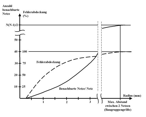
The R setting when generating SHORTS for a prototype test is relatively uncritical: a relatively high value is set. As mentioned above, this decision becomes critical when using FPT for the production engineering test (or in the case of increasing numbers per module type).
If the average size of the volume of "neighboring nets" (BN)
is known, the test time for short tests is defined as follows:
test time = N*BL*(TB+TM)
N ... net number BN ... average number of neighboring nets per net TB ... average probe movement time TM ... test time for a SHORT test
NETTEST
The Nettest patented by Siemens AG covers shorts between 2 random nets with only one contact per net. The test time is thus linearly dependent on the net number and the total probe movement time and test time per net:
test time= N*(TB+M*TM)
N ... net number TB ... average probe movement time M ... number of test steps per net TM ... average test time per test step
Multiple test steps are performed at every net with fixed probe position and a common reference potential (ground). The electrical behavior (R/D/C) is thus determined for all nets in the tested module. In the event of a short circuit, at least one of the actual values in at least one of the two affected nets will be outside the target range. The standard short test steps are only implemented in the event of an fault for nets with faulty electrical values (test steps against neighboring nets) to support diagnostics. The decision regarding the value R (radius) is not critical for the diagnostic standard shorts as the number of nets with faults on average is low (in particular in the case of high production quality). In contrast to the standard test, radius is not relevant either for the GO/NO-GO test time or for the targeted test accuracy level.
The identical test accuracy level for shorts can only be achieved by the standard test if the "neighboring net" number is extended to all nets in the module tested. This test step set contains N*(N-1) probe movements (N is net number) and is in most cases practically inexecutable.
Example: the test time is approx. 13 hours for net number N=1000
and test step time (probe movement+measurement) 100 ms.
COMPARISON OF TEST TIMES FOR STANDARD TEST AND NETTEST
A comparison of both methods was performed using the following sample configuration: module with 1000 nets, average movement time (TB) = 100ms, test time = 2ms, number of neighboring nets = 7 and number of tests per net (in the case Nettest) = 3.
test time for standard test = 1000*7*(100+2) ms = 701,4 sec
test time for nettest = 1000*(100+3*2) ms = 106 sec
In practice, the above-mentioned reduction in short test time results in a reduction factor for the overall test program:
- 3 to 5 for digital modules
- 2 to 4 for analog modules
Remark: The reduction factor increases with component pack density
and the size of the module because this increases the number of "neighboring
nets".
SUMMARY
The flying probe test has been implemented increasingly over the last few years mainly for testing prototypes.
The nettest has made it possible to extend the range of application of FPT to the production engineering test. The leading tester manufacturers (see figures) have added the nettest option to their test systems in cooperation with Siemens AG (I&S IT PS 8 MCH). This paper compared the standard test and the nettest in relation to the fault coverage and test time of the short test.
Thanks to the significant increase in the efficiency of the test, FPT and the nettest will play an increasingly important role in the future when selecting the best testing strategy for testing modules.
BIBLIOGRAPHY
A. Vuksic
Baugruppentest mittels Flying Prober
(Testing modules using the flying prober)
EPP 9/1998, pages 60 to 68